Explain Different Component Parts of a Centrifugal Pump
In the same way parts of the pump for Centrifugal Pumps are as follows. Pump parts have been briefly described below.
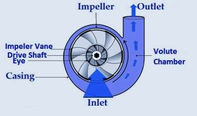
Centrifugal Pump Working Principle With Diagram Linquip
Impeller is a rotor used to increase the kinetic energy of the flow.
. General Components of Centrifugal Pumps A centrifugal pump has two main components. A centrifugal pump is the simplest machine which is used in various industries as well as in many daily applications to transfer fluid from lower head to higher head. A volute or diffuser style casing.
The first item to look at is the size of the pump. Centrifugal Pumps - Seal Centrifugal pump can. These major parts are.
The main parts of the Centrifugal Pump are. Suction pipe with a foot valve. Developed by the pump at different impeller sizes and rotational speeds.
The simplest and regularly used type is a. Schematic drawing of centrifugal Pump. It is mounded on the shaft which is coupled to an external source of energy which imparts the liquid energy to the impeller there by making it to rotate.
These components are designed to perform specific tasks. Based on the above different parts positive displacement pumps are classified into many types. The pump has a driving component that is a motor sometimes may be an engine and a power source is connected to the motor.
Main Parts of a Centrifugal Pump Impeller. The numbers 2x3-8 indicates. The rotation of the centrifugal pump impeller causes the liquid it contains to move outward from the center to beyond the circumference of the impeller because of the centrifugal effect.
Ef PW PS. The flow of liquid takes place in radial outward direction which is reverse of the inward radial flow reaction turbine. Pump Knowledge Menu Centrifugal Pumps Suppliers.
These are a crucial component of the pump as it converts energy derived from a source. WORKING OF THE CENTRIFUGAL PUMP. In pumps the casing is basically used to seal it to prevent leakage and sometimes retain pressure.
Centrifugal pump comes in different design to suit end users need. Suction pipe with a foot. Open Semi Enclosed and Enclosed Impeller.
But actual centrifugal pumps were not discovered until 17th century. The centrifugal pump is simple in construction than the reciprocating pump. Centrifugal pump is a hydraulic machine which converts mechanical energy into hydraulic energy ie.
It is used in different areas where fluid is. The mechanical end of the pump includes the pump shaft sealing bearings and shaft sleeve. Single stage open impeller pump.
A casing can be explained as a shell cover or a housing which protects and supports most of the components. Seal Shaft Casing Impeller Bearing Coupling By She rbahadur Thapa. Typical Centrifugal pumps vary in design and construction from simple pumps with relatively few parts to extremely complicated pumps with hundreds of individual parts.
The casing contains the liquid and acts as a pressure containment vessel that directs the flow of liquid in and out of the centrifugal pump. When a pump breaks down sometimes buying replacement parts or components is an alternative to buying a new pump. Centrifugal Pump Working Principle Main Parts with.
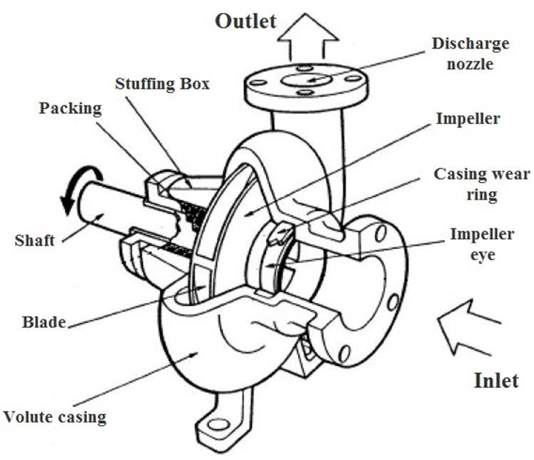
The Structure of Centrifugal Pumps A centrifugal pump consists of a set of components that some eg shaft bearing etc are responsible for maintaining the mechanical structure of the pump and others impellers and casing determine the hydraulic function of the pump. A rotating component comprised of an impeller and a shaft. However there are some major parts which are designed to perform specific tasks.
Parts of a Pump. Most centrifugal pumps consist of a few basic components. The centrifugal pump.
I have covered the following centrifugal pump diagram with parts. The Main parts of Centrifugal Pump are. Centrifugal Pumps Major Parts Their Functions Centrifugal pump is made of hundreds of parts no matter how big or tiny.
In 1475 Italian engineer Francesco di Giorgio Martini designated mud lifting machine as a centrifugal pump. And because of this movement of the fluid to the outer periphery there is a drop of pressure at the eye of the impeller. The size of the pump 2x3-8 is shown in the upper section of the graph.
Centrifugal pump has more weight due to a given discharge. Ps is the shaft power. Housingcasing - The outer shell of the pump which protects most of the components from the outside elements.
Pressure energy by the use of centrifugal force acting on the fluid. In the US the shaft power is the power given to the shaft of the pump in BHP. The energy changes occur by virtue of two main parts of the pump the impeller.
An impeller is a rotor used to increase the kinetic energy of the flow. Single stage double suction centrifugal Pump. It is also used to support some of the key parts such as shafts bearings etc.
The efficiency of a centrifugal pump can be defined as the ratio of the output power water to the input power shaft. This is the rotating component in a centrifugal pump which is equipped with vanes or blades which rotate and move fluid within the pump. Diffusers have multiple vanes and are positioned so they begin close to the outer edge of the impeller.
Centrifugal pumps are suitable for large discharge with a small head. An impeller is a rotating component of a centrifugal pump which transfers energy from the motor that drives the pump to the fluid being pumped by accelerating the fluid outwards from the. Where reciprocating pump has less weight of pump for a given discharge.
Single stage closed impeller pump. Pw is the water power. Because the centrifugal pump has less number of parts.
The impeller is mounted on a shaft. Where Ef is efficiency. It can be demonstrated by using the following equation.
It denotes by hs. Impeller The impellers are the rotating parts of centrifugal pumps. The mechanical end includes those parts that support the impeller within the casing.
These parts can be subdivided into the wet end and the mechanical end. The outlet discharge port is 2 inches. Centrifugal Pump Components.
It is a wheel or rotor which is provided with a series of backward curved blades or vanes. This article is part of Pumps 101 an eleven-part series of articles designed as an introduction to the fundamentals of centrifugal pump design selection and application. It is the vertical height of the centre line of the centrifugal pumps above the water surface in the pump from which water is to be lifted.
Pump characteristicssuch as flow pressure efficiency and brake horsepowerare shown graphically on a pump curve. It is the vertical height between the centre line of the pump and the water surface in the tank to which water is delivered. Some of the most common components found in centrifugal pumps are.
The casing of the pump should be of materials.
Centrifugal Pump Parts Learn About Nine Parts Youtube

What Is Centrifugal Pump Parts Working And Uses Engineering Choice

6 Main Parts Of Centrifugal Pumps Linquip
6 Main Parts Of Centrifugal Pumps Linquip
Comments
Post a Comment